SWR Meter
Schema
This SWR has a classic balanced schema for measuring power of forward and reflected waves.

Balancing is set by trimmer capacitor C3
Details
| Ref | Qnty | Value | Description |
|---|---|---|---|
| C1 | 1 | 220pF | Unpolarized capacitor |
| C2, C4 | 2 | 105 | Unpolarized capacitor |
| C3 | 1 | 3-10pF | Trimmable capacitor |
| D1, D2 | 2 | 1N34 | Diode |
| J1 | 1 | Antenna | coaxial connector, SO239 |
| J2 | 1 | RX | coaxial connector, SMA female |
| J3 | 1 | TX | coaxial connector, SMA female |
| J4 | 1 | Conn_02x01 | Generic connector. |
| J9 | 1 | Conn_01x03 | Generic connector, single row, 01x03 |
| K1 | 1 | JQC-3F(T73) | PCB Relay |
| L1 | 1 | 470uH | Inductor |
| R1 | 1 | 182 | Resistor |
| R2, R7 | 2 | 683 | Resistor |
| R3, R4, R5, R6 | 4 | 68R | Resistor |
| T1 | 1 | 1:10:10 | Transformer, single turn primary, split by 10 turns secondary |
Board
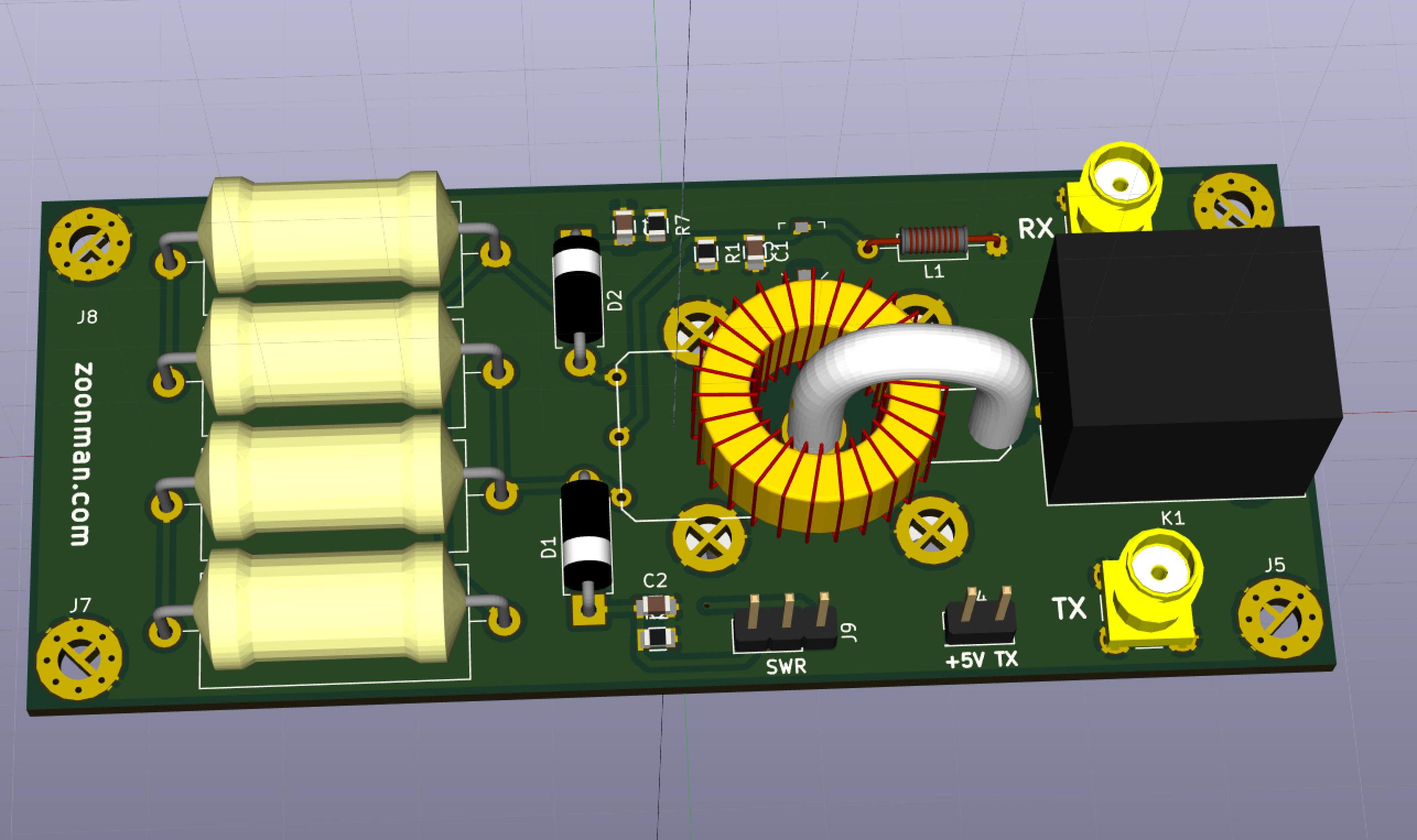
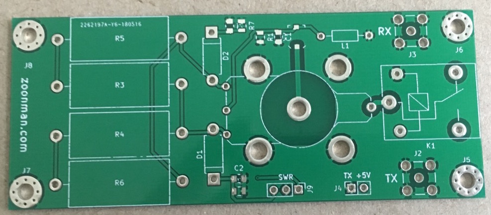
| 3D Model | Front PCB | Back PCB |
|---|---|---|
 |
 |
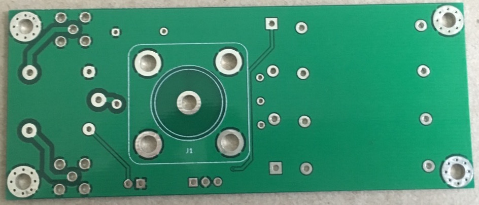 |
It has a slightly unusual design and mounted on the back wall of transceiver. I used sandwich from the TRX wall, one-sided PCB boards which serves as isolator and SWR meter board. SWR meter board has a hole for SO 239 connector and relay to switch between reception and transmission. Also I installed SMA connectors to connect the main transceiver board and amplifier with filters. I used T50-6 carbonyl iron ring transformer and a loop made from central core of 50 ohm coax cable.
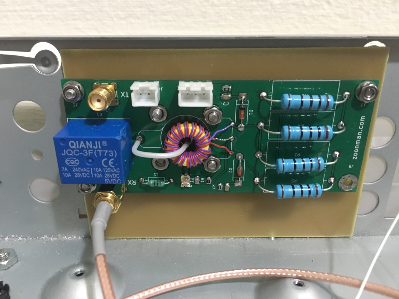
I plan to shield the board when I will finish tuning. This little loop picks up the noise from power supply really well therefore I have to shield it.
Video
I recently discovered that somebody in China has made a kit from this board and sells it on AliExpress
You can left first comment.